Old Photons Observatory Automation

Old Photons Automation

Old-Photons. At first I thought “Old Photons” was a really cunning name for an observatory.

Our galaxy is about 100 thousand light years in diameter and contains many of the objects an amateur astronomer will focus their CCD on. The images we capture of these objects are in fact images of the way these object were thousands to a 100 thousand years ago.  From the place photons originate within these objects it takes this much time for these photons to travel to us. For objects outside our galaxy we wait even longer. The nearby Andromeda galaxy is 2.5 million light years from us and the images we take today show us its appearance 2.5 million years ago.

But then I had a troubling thought. The electrons I collect in my CCD are due to old photons, but then,… Do photons age?… Do they get old?.. Are there such things as old photons?

The faster you travel the slower time progresses for you, as you arrive at the speed of light, time slows to a stop. Since photons zip along at the speed of light they don’t experience time and so they don’t get old. It’s a bit confusing because from our perspective they do get created and are absorbed in my CCD. How can something that does not experience time have a birthday and an end?

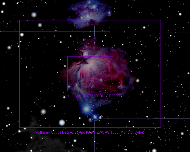
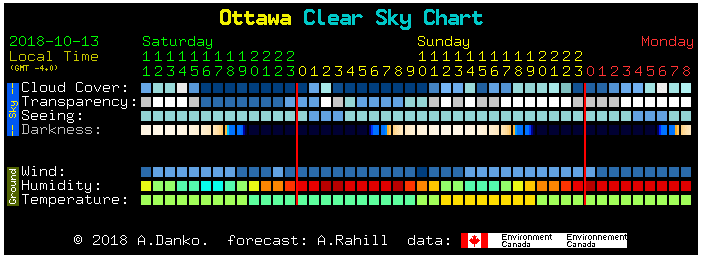
The image above is a screen capture of the observatory at work. The screen shot was taken while it was observing M31 shown below.

  • When the screen shot was taken, the lights in the observatory were temporarily turned on. The webcam gives the ability to see what is going on, it is almost like sitting outside.
  • Lower to the left is Celestron’s NexRemote PC interface to the mount. It is an emulation of the hand controller and provides a COM port access of the mount to the control SW.
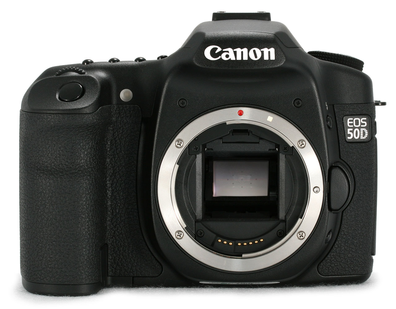
  • Below this is remote shooting control for the canon DSLR that rides below the telescope.
  • On top to the right of the webcam viewer, is the central controlling application, ACP Scheduler. It shows the dispatcher is activated and observing jobs are dispatched as objects pass overhead. It is set to prefer objects that are near meridian. Usually the only thing to do is launch this application, and enable the dispatcher. It then looks after launching all other needed applications. The dispatcher holds access to the lists of all queued observing targets, it prioritizes them and dispatches according to rules including avoiding moon lit nights, objects position in the sky.
  • Below to the left is the small control that is part of the Celestron mount ASCOM driver. It provides the ASCOM mount interface that other applications connect to.
  • The larger application below this next to the Canon DSLR app is MaxPoint. This application provides pointing corrections. It interfaces to the ASCOM Celestron driver, and is trained with a grid of 100 points across the night sky. A pointing error refers to the difference between where the mount points in the sky compared to the commanded pointing instruction. Based on the 100 observations a model of the errors is created and used to correct the mount. Because of MaxPoint the rest of the applications not do not have to contend with these errors. Because this is a permanent setup training is done very infrequently. Once a year and only if physical adjustments to pier or mount are made.
  • The large application to the right on the bottom is ACP Observatory Control.  This is the application that executes the activities needed to run the observatory. It is mainly script based. Scripts are triggered by conditions or desired jobs from the dispatcher. Currently it was running AcquireScheduler script, which accepts object target, and observation parameters from the dispatcher. It also monitors the state of the weather and also coordinates telescope and dome (roof) movements.
  • Above, the small window shows the state or activity of the dome.
  • FocusMax is the larger application on the top. This application is has access to the stepper motors of the focuser and the CCD. FocusMax learns information about the optical path and CCD and formulates how to find focus from the slope of measured star Half Flux Diameter versus motor position. It can monitor temperature and make adjustments thru the night as temperature effects the physical length of the telescope. The observation plans given to the dispatcher are configured to ask ACP Observatory Control to do a focus run prior to every set of images. Usually a half flux diameter of 4 pixels is as good as it gets.
  • The large application lower to the right is my partially self coded weather application. In the plot the ambient temperature was -11C, the sky temperature was a chilly -43C and the difference was 32C. The application uses a threshold of 15C to declare overcast conditions. This application runs in the background updating 1 per second. A written updated file provides ACP Observation Control with a trigger to “shut-er-down” on bad weather. Jobs that are interrupted are re-queued.
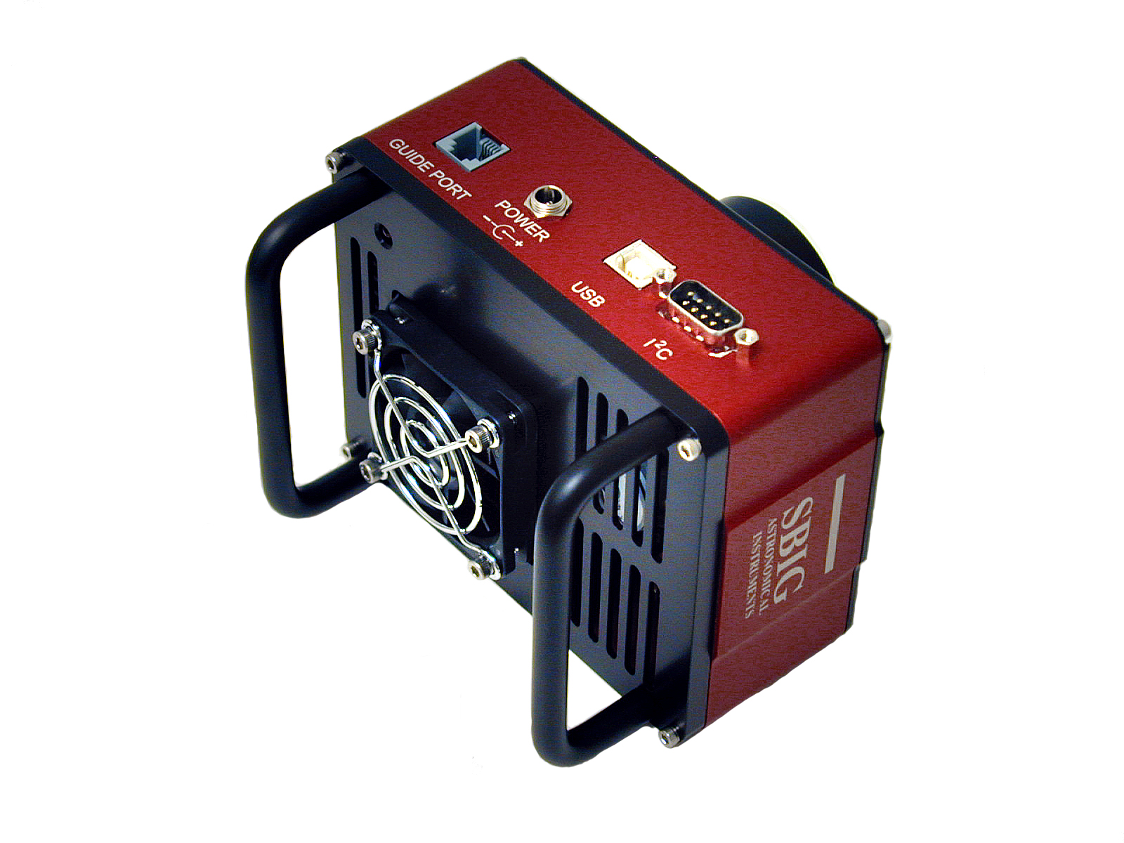
  • Camera control is part of MaximDL which is the imaging engine. It shows two cameras are connected and running. Camera1 is the main CCD, Camera 2 is the auto-guider. Camera 1 is cooled and was set to -20C, since it was a cold night the cooler was running only at 5%.
  • MaximDL is the large window to the right. It shows the most recent image, and periodic images from the auto guider. MaximDL initiates filter changes, focuser updates based on differential filter focus requirements, initiates main CCD exposures, runs the auto-guider, evaluates and initiates guiding corrections. Upon completing each image capture it calibrates each image and plate-solves the image. Plate solving data is stored in the image file for use in alignment and stacking post-processing.
  • The strip graph below shows guiding performance over the past 15 minutes. The mount has been periodic error correction programmed and 0.5 to 0.6 arc-sec rms guiding errors are typical performances.
NGC224 M31 181115 (LRGB, 1L 20min @ 1x1binning + 1RGB each 10min @ 2x2binning,  Total exposure 50min, 7×7 median filter and digital development)

Data files for NGC224 M31 181115 are available at My Google Drive

Adrien.

Inside Old Photons

2X5A1197.JPG
Open and ready to observe, but its not dark yet!

The observatory was inspired by many that can be found on the web. A roll-off roof type was initially though as easier to construct compared to an iconic round domed type. There were few special construction steps needed. The most complicated parts were the roll-off rollers and rails, AC motor and gearing, and the solution to inhibit the roof from hitting a non parked telescope.

Telescopes and German Equatorial Mount are described in post Equipment List and Links. The cloud sensor is shown in the picture above on the left.

2X5A1200.JPG
Pier / Mount / Telescopes and Cameras

I have found that a simple loose braid of interconnect cables is better than another solutions. The braid results in an arrangement that provides better flexibility and causes less force as the mount slews. A total of 15 connections are present.

  • STF8300 CCD USB, 12V DC  (2 connections)
  • STi Guider CCD USB, Guider (2 connections)
  • ASI1600 CCD USB, 12V DC (2 connections)
  • Focuser Thermo sensor (1 connection)
  • Stepper Motors (2 connections)
  • Park Detector USB, 12V, direct connection to Dome Control (3 connections)
  • Dew Heater 12V (1 connection)
  • Canon 50D USB, 8V DC (2 connections)
2X5A1221.JPG
Focal Reducer / Focusers / CCD and Park Detector
2X5A1224.JPG
Brain & Brawn, Computer & Roof Control

The computer in the observatory performs all observatory control functions. A single 1GbE Ethernet connects back to the house for remote monitoring and supervision. The Ethernet cable is buried along with but separate from a single 15A 120V service.

The hoist motor’s output is connected to a 10:1 gear box. The gear box output drives a 40 tooth chain cog and chain drive to roof.  Relays provide Arduino controlled AC motor control. Limit switches are used to stop on “opened” and “closed”.

2X5A1222.JPG
V groove rollers and rails

The roof moves on 6 V-Groove rollers. The rails are a combination of 90degree angle iron welded to a flat iron bar by a local machine shop.

Adrien.

Resolution & Seeing

We are familiar with the expression, “Too much of a good thing”, which leaves you with the thought that excess may do harm. I can attest the expression, “Your mileage may vary” is true because I know my wife can drive much further on a tank of gas than I can.  One other hand “One size fits all” is rarely true and I do not have to mention the things that no longer fit. As an engineer I am very familiar with the idea of “diminishing returns” as it plays a important role in design. Its important not to over achieve in one aspect at the cost of others.

But what do these have to do with astronomy?

The calculation sheet below is available in the Old Photons Observatory Public Google Drive at Calculation Sheet. Calculations are made for both the primary system, SBIG STF-8300M FW8-8300 CCD on the Celestron EdgeHD 11 telescope and secondary system  ASI1600MC Pro CCD on William Optics 90mm telescope.

Capture4.PNG
Basic Calculations for Old Photons Observatory

Both CCDs are the same size at 22mm on their diagonals, however the CCD pixel resolutions are quite different. STF8300/C11 has a scale of 0.57arcsec/pixel where ASI1600/MR90 has a scale of 1.26arcsec/pixel. This is calculated from pixel size divided by focal length. The factor 206 comes from (180/π)*60*60/1000 which is a scale factor that converts radians to degrees, degrees to arc seconds, and meters to mm.

It is difficult to get a grip on how big an arc-second is. One arc-second of angle is approximately the thickness of a dime at a distance of nearly a half kilometer. If that is hard to visualize then perhaps the same dime at arms length is about 500 arc-seconds. Nope,… neither of these does it for me. I guess I should have written that it is difficult to get a grip on how damn small an arc-second is.

Because telescopes have a finite aperture, they have a limited resolving power. The larger the aperture the higher the resolution of the image the telescope can place on the CCD sensor’s surface. Dawes limit is one calculation of this resolution. The C11 has a limited resolution of 0.43arcsec where the MR90 has a limited resolution of 1.33arcsec. These are the performances the telescopes would have if they were perfect and only limited by their finite aperture. This is where the term diffraction limited comes from and your telescope should be diffraction limited.  The central obstruction of the C11 and its collimation will degrade its resolving power, but we can be assured it will never be better than the Dawes limit.

The STF8300/C11 has a scale of 0.57arcsec/pixel with a Dawes limit of 0.43arcsec. By the numbers, the STF8300 is the limiting part of the system because its resolution is poorer than the C11.  The ASI1600/MR90 has a scale of 1.26arcsec/pixels with a Dawes limit of  1.33arcsec. Unlike the primary system, telescope is the limiting part of the system because MR90’s resolution of poorer than that of the ASI1600. The only 3 factors that contribute to these outcomes are pixel size, aperture and focal lengths.

Aperture is a good thing in most minds, and more is better, but pixel size needs to shrink smaller to keep up. In this respect too much of a good thing can leave harm in our pocketbook and wasted untapped telescope potential.

When childrens’ stars twinkle, the astrophotographers are likely in bed. When the stars are twinkling we would say that Seeing is poor. The Pickering Seeing scale is used as a way to quantify seeing.  Because seeing conditions are dominated by atmospheric conditions the clear sky clock, for example, predicts seeing based on current environmental data.

Capture5.PNG
Clear sky clock example for Ottawa.

Wikipedia indicates that best conditions result in about 0.4 arcsec seeing. However this is only expected at high-altitude and small island observatories. One or two arcsec seeing is a more appropriate to assume for the rest of us.

This brings us to topics of diminishing returns and variable mileage. The 0.57″/pixel, Dawes limited 0.43″ STF8300/C11 and 1.26″/pixel Dawes limited 1.33″ ASI1600/MR90 systems are both into the diminishing returns area. Only under better than average seeing will the STF8300/C11 show its value. Image quality will depend on nightly variable seeing conditions and so in this regard your mileage will vary.

The calculated field of views are 32’x24′ and 98’x74′. The ASI1600/MR90 will have 3 times the FOV of the STF8300/C11 and it is for this reason both systems available. In astronomy one size does not fit all and a change in equipment is desirable.

Capture3.PNG
Screen Shot from TheSkyX showing FOVs

Adrien

Equipment List & Links

Building a observatory can be a interesting activity, but I must say Alain Maury has the better strategy. His web site says “Never call us in the morning. I work at night and sleep in the morning”.  San Pedro de Atacama Celestial Explorations is a observatory site in the Atacama Desert in Northern Chile. The volcanoes on the horizon mark the boarder with Bolivia. It was the most amazing view to wake up to from his B&B window. Roxanne and I spent 4 nights there a few years ago. He hosts automated telescopes to individuals around the world. Sunset is marked by the sounds of dome roofs opening up and telescopes starting their nightly work.

I highly recommend a visit.

IMG_0589.jpg

This post is a summary of my meager observatory equipment, optical and otherwise.

IMG_0639 (2) Croped.JPG

Main Optical System, STF-8300 on C11 EDGE at F/7

  • Dew Shield: The dew shield is an aluminum type from AstroZap. hd-white-nn-lrg_324bffc8-b217-4d26-8622-27d300206a32_300x300.jpg
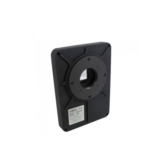
The aluminum version holds its shape better than the flexible plastic versions. Non marring hard plastic thumb screws securely hold the dew shield to the scope. It is important to protect the large dark-sky-facing collector plate of the SCT telescope from dew.
  • Telescope: Celestron EdgeHD 11 and 0.7 Focal Reducer.
91050-XLT_CGE_Pro_1100_HD_4_570x380@2x.jpg

The main telescope is an 11 inch flat field Schmidt-Cassegrain.  It’s EDGE optics  provides a flat field benefiting large sensor CCD cameras. The linked white paper outlines Celestron’s design. The telescope is a 297mm aperture, F/10 system.

94241_reducer_lens_1100_03_570x380@2x.jpg

A 0.7x focal reducer is mounted to the rear cell of the telescope. It produces a F/7 system, increases field of view by 43% and increases speed by 1 F-Stop. The change in F-Stop enables exposures accumulate twice as fast.

  • Focuser: The focuser is crayford type from MoonLite.
11-14EDGE-1.jpg

The focuser is connects directly to the 0.7x FR, and it is designed to have a very low profile and consume minimized backfocus. This is important because the EDGE design requires CCD sensor to be 146.05mm from the 0.7 FR rear cell. The focuser is driven by a high resolution stepper motor and provides 2µm focus step size.

This camera has a 8.3Mpixel 18mm x 14mm sensor with 5.4µm pixels. The 8 position filter wheel provides Luminance, Red, Green, Blue and Ha, S-II, O-III. One position is left empty with no filter installed for “Clear”.

  • Guider:  The off axis guider is integrated into the main camera / filter wheel assembly. Off Axis Guider has a integrated 0.7x focal reducer which expands the field of view of the guide monochrome STi CCD. This increase of FOV increases the probability a guide star can be found.
STF-combo-600x600.jpg

Secondary Optical System, ASI1600MC on Megrez 90mm at F/6.9

  • Secondary Optical System – Piggy Backed
m90apo.jpg

  • The focuser is MoonLite SCT type similar to the main system. It is also equipped with the same high resolution type stepper motor focus option.
  • The camera is a one shot color cooled ASI1600MC Pro CCD. It is a 21.9mm diagonal 16Mpixel, 3.8µm pixel CMOS CCD.1600MM-Pro7-460x446.jpg

The Field of View of both systems are shown below.

Capture3.PNG
FOV for Main and Secondary Optical Systems

WideField

  • 15.1-megapixel digital single-lens reflex camera Canon 50D and EF 50mm F1.4
ZURFRONT.JPG
canon-ef-50mm-f1.4-usm.jpg

Mount and Pier

  • The mount is a German Equatorial Celestron CGE Pro. This mount provides a 90lb instrument capacity, +/- 5 arc second tracking accuracy typical unguided periodic error.
celestron_91529_cge_pro_mount_917600.jpg
  • The pier is locally manufactured similar to version sold at Permanent Pier .

Observatory electronics

  • The observatory computer is a Dell Optiplex 7010. This computer runs Windows 7 Professional. Key software applications are
    • Logitech Web Cam Capture for remote visual monitoring of observatory
    • Velleman K8090 application relay board control for 12V supplies
    • ACP Expert Scheduler for observation planning and unattended execution.
    • ACP Observatory Control Software for automation of observatory tasks.
    • PinPoint for plate solving and pointing corrections.
    • FocusMax for auto focus.
    • MaxImDL for Camera control and exposure
    • Celestron NexRemote for Serial connection to Mount
    • MaxPoint for mount pointing modeling.
    • Arduino Weather Station Application to read sensor and write Boltwood weather file.
    • Dimension 4 for automatic PC time update.
    • ASCOM Drivers and USB ports are used to access
      • Mount
      • Cameras
      • Focusers
      • Dome / Roof control
      • 12V switch control
    • VNC Remote assess via Gbps Ethernet connection
  • 12V DC Supply for the observatory is a 15A amateur radio supply manufactured by Kenwood, KPS-15.
  • Dew Heater and controller are from Kendrick. 12V power is relay controlled.
  • Focuser Controller is the MoonLite dual port controller. It is able to connect and drive focusers on main and secondary optical systems. MoonLite ASCOM driver provides the control interface.
  • DC Power distribution and control is achieved by a K8090 USB controlled relay board. The eight relay positions are used for  1) Mount, 2) Dew Heater, 3) Canon DSLR, 4) Focuser, 5) ASI1600MC, 6) STF-8300, 7) Observatory Lights, and 8) Roof Control/Park Detector. A custom written ASCOM driver is used to interface to the relay board.
k8090_3.jpg
  • 8V Canon supply is a 12V to 8V linear regulator. 12V power is relay controlled.
  • Monitoring for overcast conditions is done with a Arduino Controller based DIY solution. The key detector is a MLX90614 infrared temperature sensor. Sky conditions are derived by measuring ambient and sky temperature. A custom written ASCOM driver provides a control interface. Switched 12V power to Arduino provides a hard reset on relay control.
  • A Telescope Park Detector is used in conjunction with roll off roof control. Because telescope must be parked prior to closing roof, and telescope must not be allowed to slew if roof is closed an interlock is needed. The key sensor component is an accelerometer and gyroscope used to measures the telescope’s orientation and is mounted to the telescope. The host Arduino is programmed with a expected “park” orientation and signals to the roof controller is the telescope is parked. If the park detector detects telescopes is leaving park position while roof is closed, the park detector interrupts power to the mount halting any further movement. Switched 12V power to Arduino provides a hard reset on relay control. Robustness of this safety function is secured as this is a standalone circuit and does not require any intervention from the windows OS.
  • A Roll-off roof controller is a custom Arduino based circuit. AC Motor, Gearing and limit switches provide physical chain control of roof. A simple two wire interface connects to and from the park detector Arduino. A custom ASCOM driver provides needed interface to allow initiating dome control. Initiating roof closure without park achieved will block close from commencing. Switched 12V power to Arduino provides a hard reset on relay control.

Adrien